**Do NOT use these instructions for updating the TD-1 firmware after initial installation**
While holding the boot button on the PI, connect to your PC.
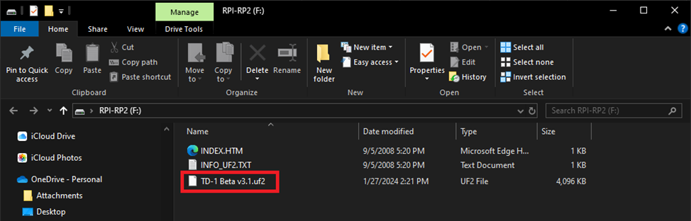
You should see a storage drive called “RPI-RP2”.
Drop the file labeled “TD-1_V1.0.4.uf2” onto this drive.
When flashing is complete the RP2040-Zero will automatically restart.
After it restarts, on a Windows machine, it may notify you that a new device called “TD-1” was connected and is installing drivers. Then it may pop up and say that the unit is ready for use.
Unplug the RP2040-Zero from the PC.
Step 2 – TD-1 Assembly Instructions
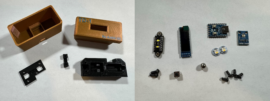
First layout your components and make sure you have everything. Make sure you have followed the installation instructions for preparing the RP2040-Zero prior to wiring and assembly.
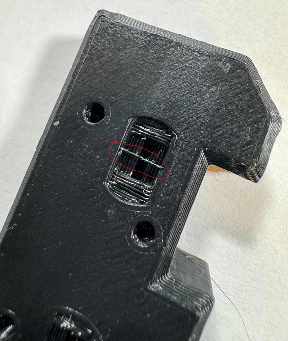
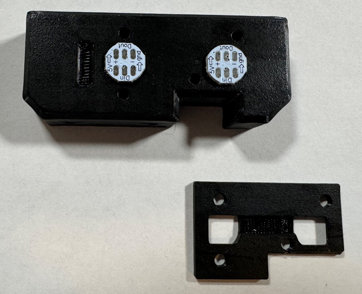
Make sure you print your Sensor Mount in BLACK.
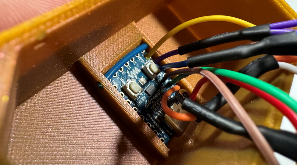
Next make sure to remove any obstructions from the LED pockets. Such as in the image below.
Make sure you wire TD-1 up using the wiring diagram. Wires will be easier to solder before installing the components. Headers and connectors are NOT recommended as there is not enough space for them.
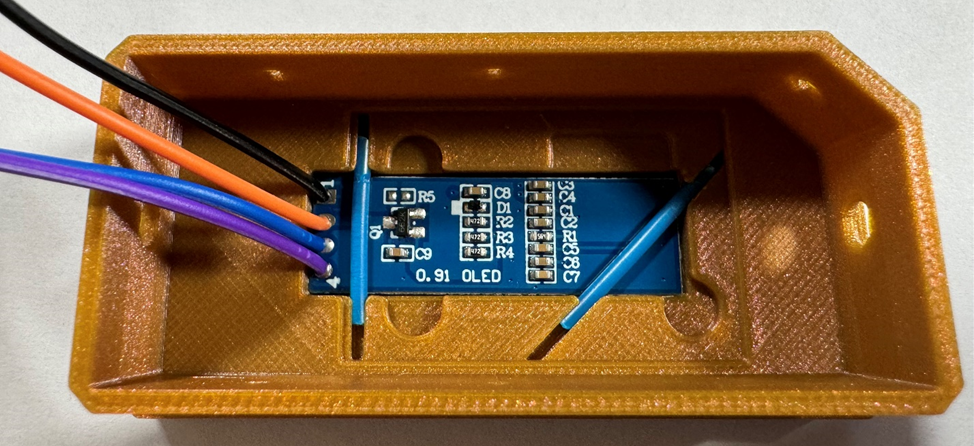
Let’s start with installing the Display. Use caution when setting the display into the pocket as the tolerance is small and the glass can break easily. You will know the screen is all the way in when you can slide a strand of filament into each of the channels provided to keep it in place.
Install the NeoPixels as shown below. Ensure the Din for both LEDs are facing the side with the notch.
Screw the LED backer into place using 4 M3x6mm Button Head Cap Screws. Take care not to over tighten these screw as they screw directly into plastic.
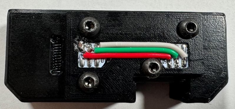
Following the wiring diagram, wire the LEDs as shown below.
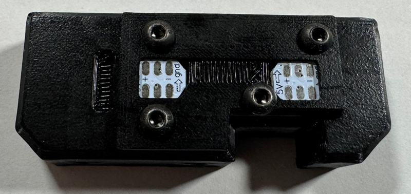
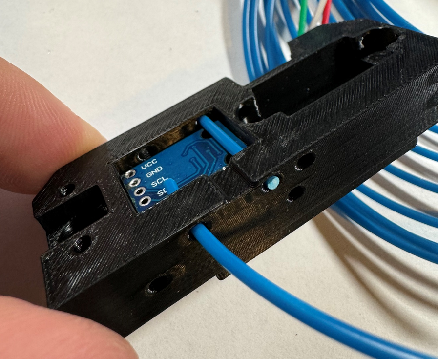
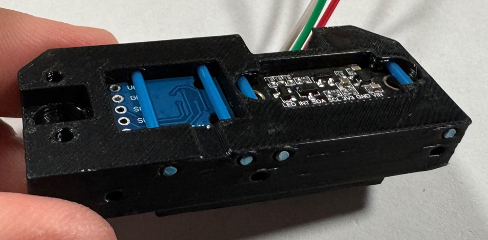
Now install the Luminosity and RGB sensors.
You will want these wires soldered in already (I left them off for the sake of these photos).
Now install the Luminosity and RGB sensors. You will want these wires soldered in already (I left them off for the sake of these photos)
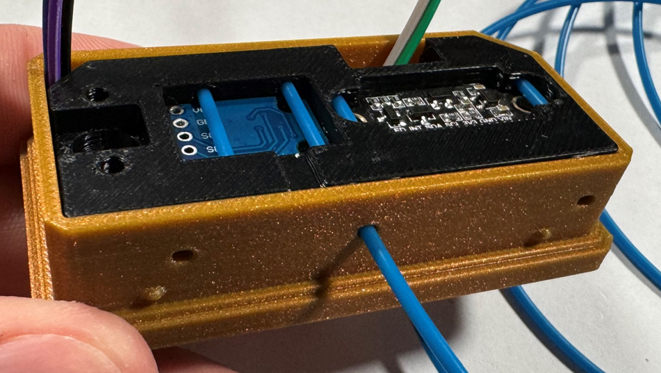
Make sure both sensors are oriented in the pockets as pictured.
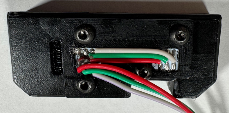
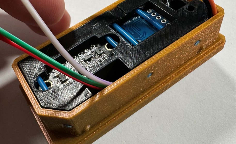
Make sure to lay the wires from the display flat to the corner as shown in the left side of the image below. Route the LED wires up out the notch on the right side of the image below. Take care to make sure all the wires lay flat as you slide the sensor mount into the top case.
Now insert three strands of filament to secure the sensor mount in the top case as shown in the image below.
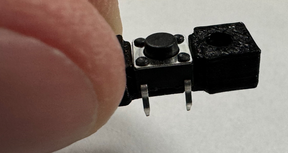
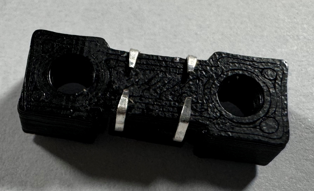
Place the switch onto the switch mount as shown below.
Wrap the legs of the switch around the switch mount as shown below.
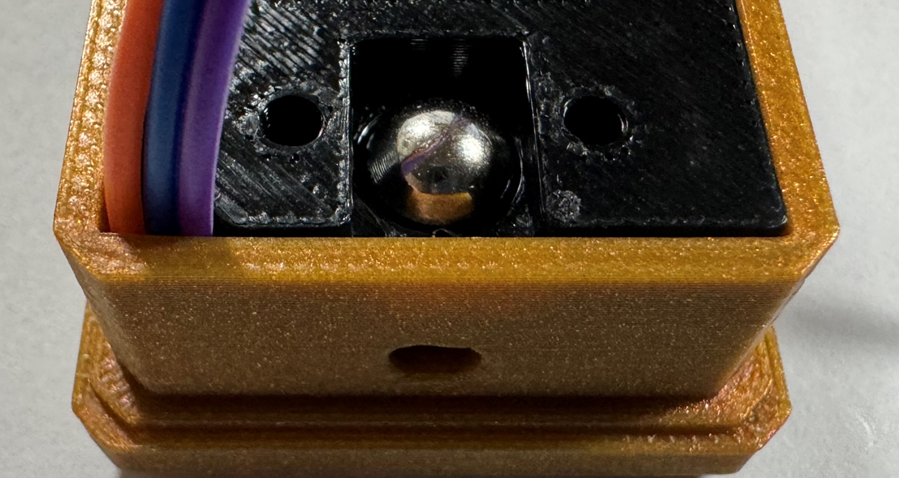
Insert the 7mm ball.
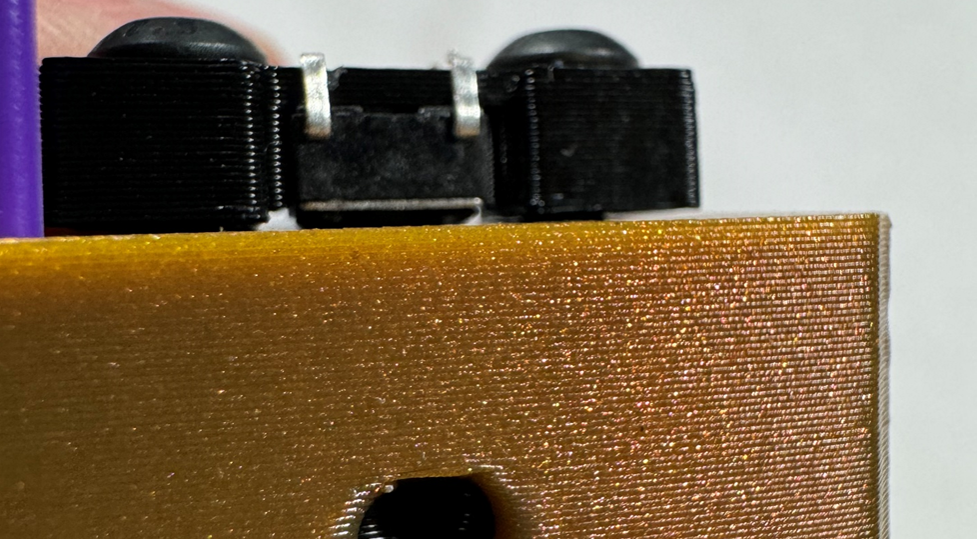
Insert the two M3x10mm Button Head Cap Screws through the switch mount and screw into place as shown below. Take care to not overtighten these screws as you are screwing directly into plastic. This switch is designed to not screw all the way down. You want to evenly screw in the screws so that the switch is parallel to the sensor mount, Tighten the screws till the button JUST touches the 7mm ball. As shown in the image below, there may be a gap between the switch mount and the sensor mount.
Insert a strand of filament and ensure the switch engages.
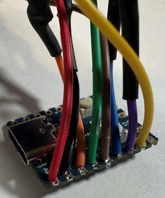
Next you will want to complete the wiring as shown in the wiring diagram and solder in place.
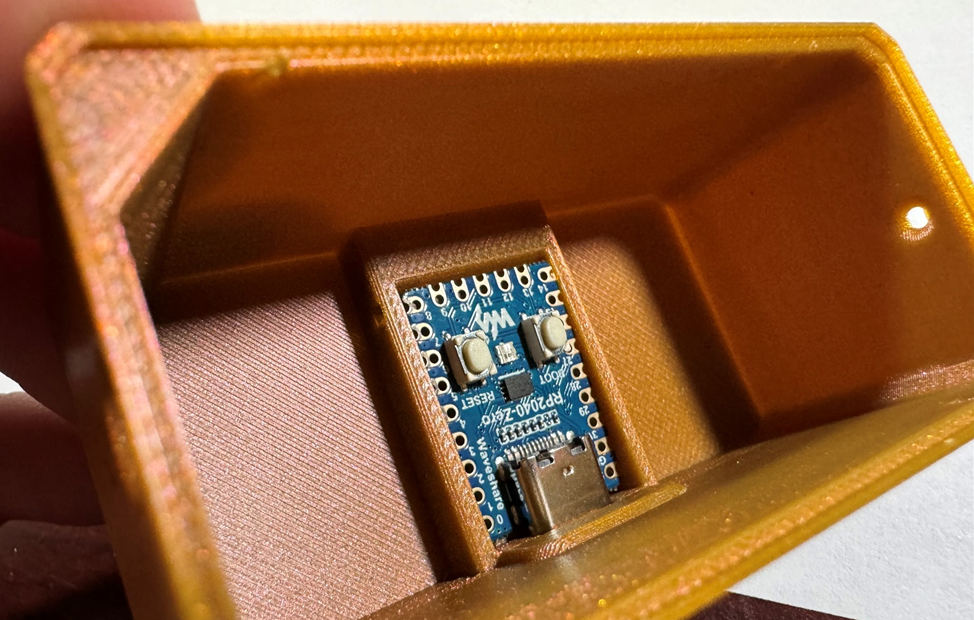
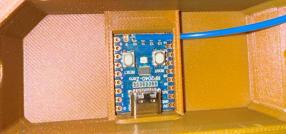
Next you can install the RP2040-Zero as shown below. (I am showing with a non-wired unit to be able to provide better pictures)
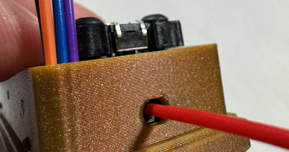
Now insert a strand of filament through the back of the box to secure the RP2040-Zero into place.
Here is an image with the wiring in place.
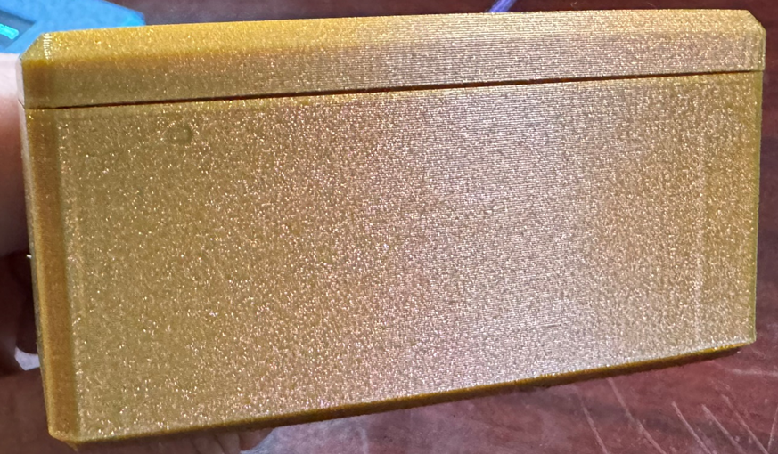
Now make sure to tuck all the wires into the bottom case. Make sure no wires are getting pinched as you slide the top case into the bottom case. Press the two case halves together firmly till they snap into place. A small gap between the two halves is by design.
Step 3 – First Boot
Connect the completed TD-1 unit to your PC.
**SCREEN WARNING**
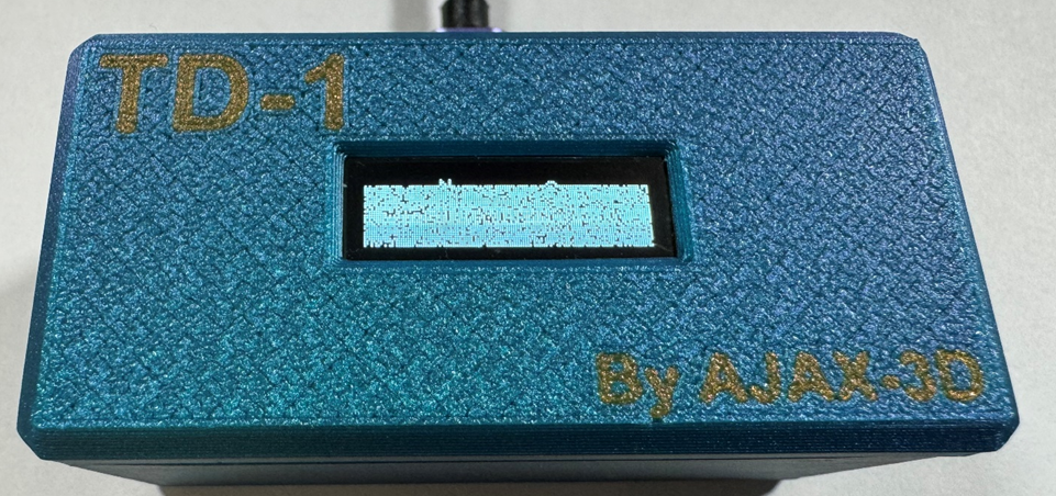
The screen should display “No License”. If it shows nonsense or is blank, like the image below, follow these steps before troubleshooting other possible issues.
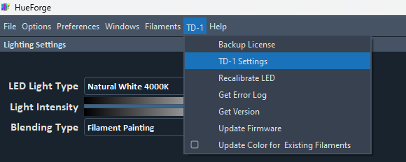
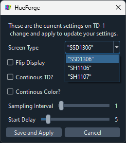
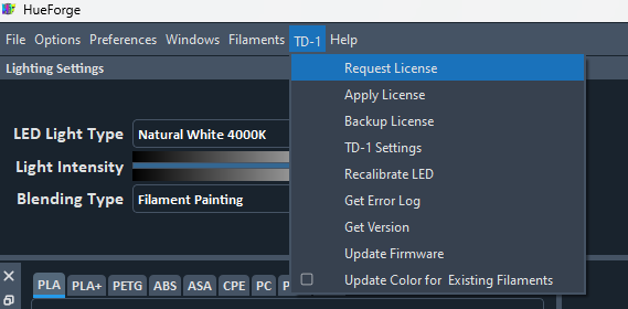
If your screen does not show clear text or is blank, this might NOT mean that something is wrong. It turns out there are vendors out there selling both SSD1306 and SH1106 displays under the same SSD1306 name. I tried really hard to make the same code work no matter which one you have. However, ultimately the solution is that I had to make a setting called "Screen Type". If you bought the SSD1306 type screen and it's not displaying correctly, try changing the Screen Type between SSD1306 and SH1106. To change this value from the default SSD1306 you can connect your unit to the same computer that is running HueForge and select the "TD-1 Settings" option in the TD-1 menu.
After making changes selecting the "Save and Apply" option will apply the settings and restart the unit so give it a minute after applying changes. The SH1107 option is for the larger screen and won't help if you have the size screen in the image above.
Once the correct Screen Type is set and the unit has restarted, you should have clear text “No License” on the screen.
If not, now it is time to go back and check your connections or even the glass of your display for damage.
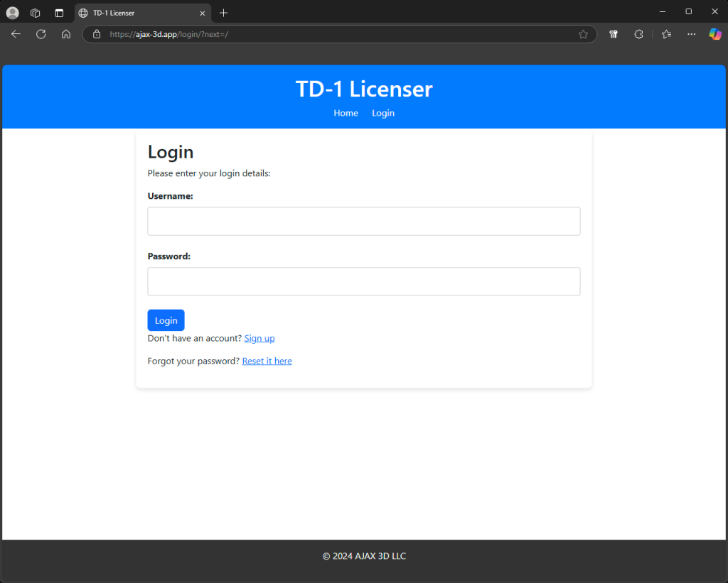
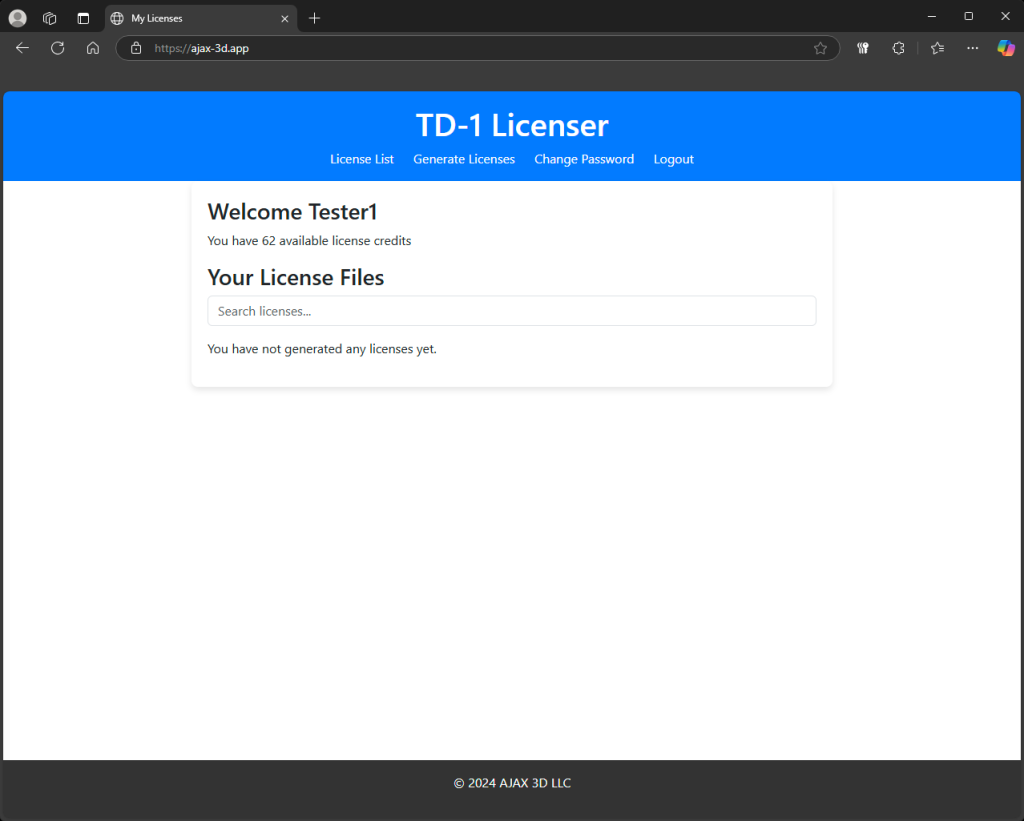
Once logged in, you should be on your "License List" page where any licenses you have generated through the app will be listed as well as how many license credits you have.
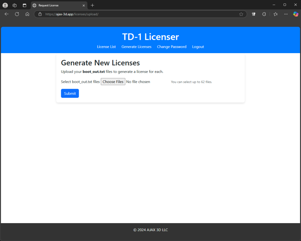
To generate a new license, select the "Gernerate Licenses" tab at the top of the page.
Select the "Choose Files" button and select the "boot_out.txt" file from your AppData directory. Then select the "Submit" button.
If the upload was successful, you should have received a download file called "xxxxxxxxxxxxxxxx.bin" the "x"s represent the SN of the pi it works with. Now in HueForge, select the "Apply License" option in the TD-1 menu and locate that new file in your downloads folder. The list will be filtered to the SN of the pi connected to HueForge.
Once you apply the license, your TD-1 should restart and should boot to a screen that states “Insert Filament” and is now ready to use.
If you run into issues at any time in this guide, please feel free to email, message in the AJAX 3D Discord, message on Patreon, or DM me on Discord.