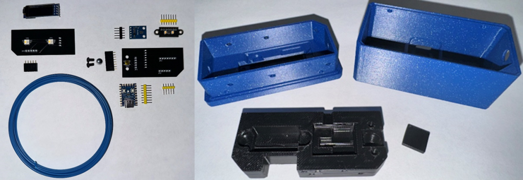
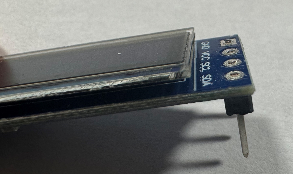
Now let’s prep the display for installation. USE EYE PROTECTION – Clip the leads with flush cutters like the image below. (If your display came without the header soldered, solder it on to match the image below first.)
Use some double-sided tape or super glue to adhere the display spacer to the back of the display.
Gently insert the display into the slot. This may take some time to get the display to align with the pocket as it’s a tight fit to insure the display does not shift during normal use.
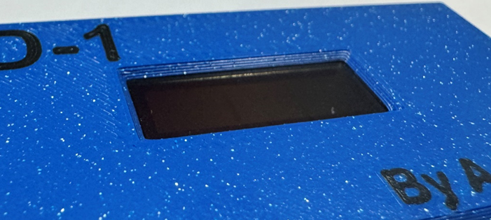
Make sure the display is fully in the pocket by checking that there are no gaps on the front of the unit.
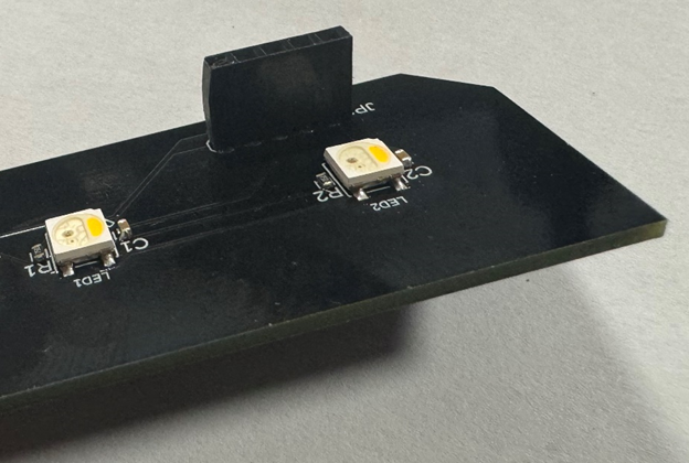
Solder the 5-pin female header to the LED PCB and trim the leads flush. Take care to ensure that it sets straight.
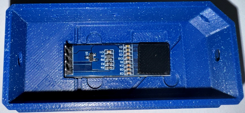
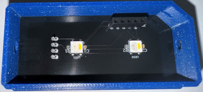
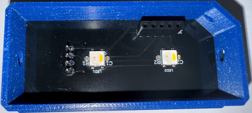
Set the LED PCB down on top of the display, making sure the leads slide through the holes.
Solder the display leads while the LED PCB is in place.
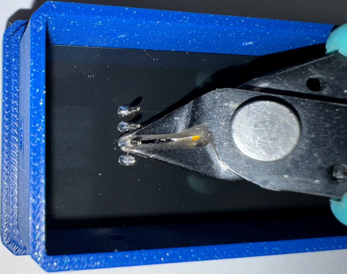
Trim the leads as flush as you can. Take care not to damage the LED or the resistor next to it.
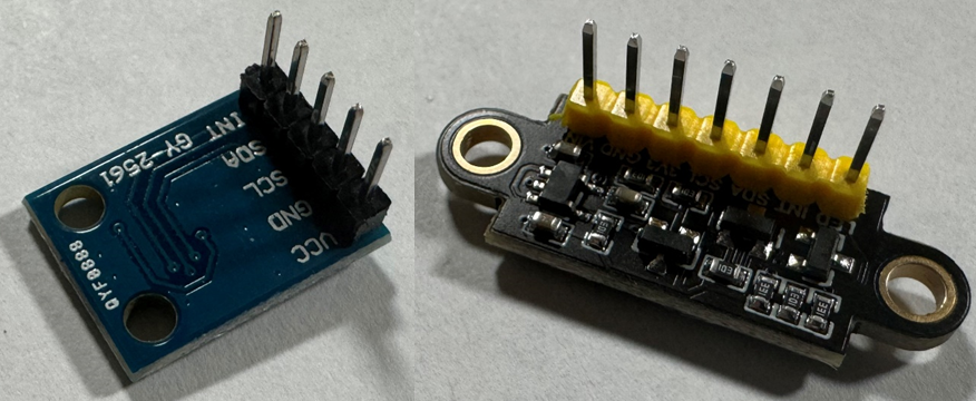
Solder the header to the Lux and RGB sensors.
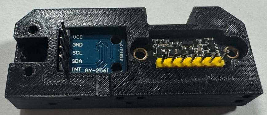
Install the Lux and RGB sensors in the sensor mount.
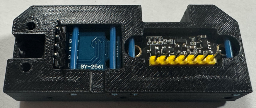
Using four strands of filament, secure each board in place. Trim the filament flush with the side of the sensor mount.
Install the 7mm Ball
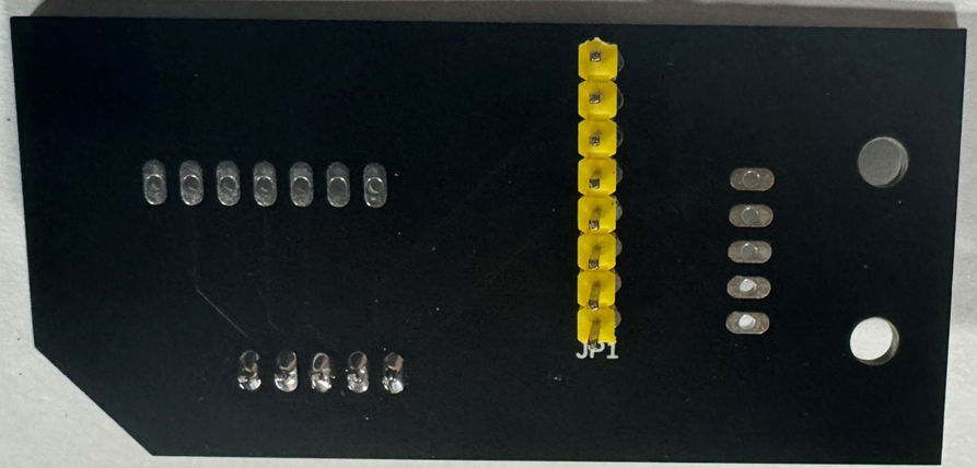
Solder the headers to the Button PCB.
WARNING: Make sure your 7mm ball is still in place. If you forget to get the ball in place, or it falls out and you solder the sensors in place in the next step, you will have to remove the filament pins that hold the sensors in place to install the ball.
Place the Button PCB over onto the sensor mount insuring that the header pins align with the holes and solder in place.
Insert the two M3 button head cap screws.
Note that you are screwing into plastic so do not over tighten.
Once you feel the screw touch the PCB, insert filament and listen for a slight click from the button. If there is too much resistance from the button, back off the screws till the filament passes through smoothly and the button is still triggered.
Slide the sensor mount into the top case making sure the male and female header align correctly. Secure the sensor mount in the top case using three strands of filament, trimming each one flush with the case.
Solder the 8-pin female header to the RP2040-Zero. Again, making sure the header is straight.
There are 9 holes on this side of the Pi. Make sure that the header is inserted in the eight holes closer to the USB side.
Trim the leads.
Install the RP2040-Zero into the bottom case and secure with a strand of filament. You can leave a little extra filament hanging out on this one if you like.
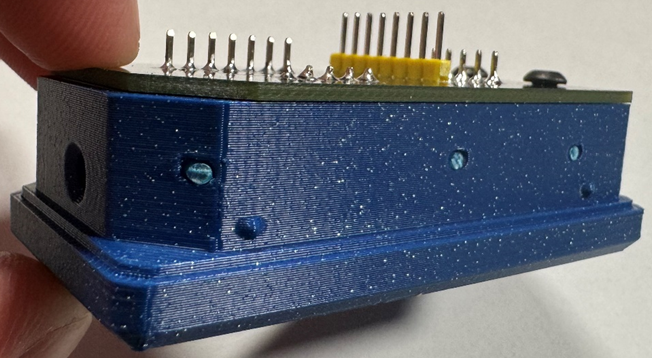
Slide the top case into the bottom case taking care to make sure it goes evenly to ensure the headers engage correctly.
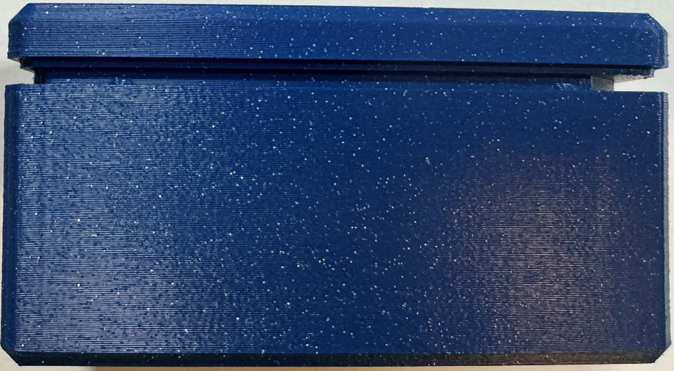
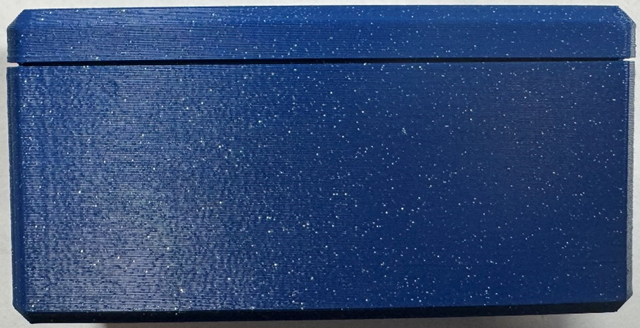
Once the top case detents touch the case give it a little pressure evenly until it snaps into place. A small gap is by design.
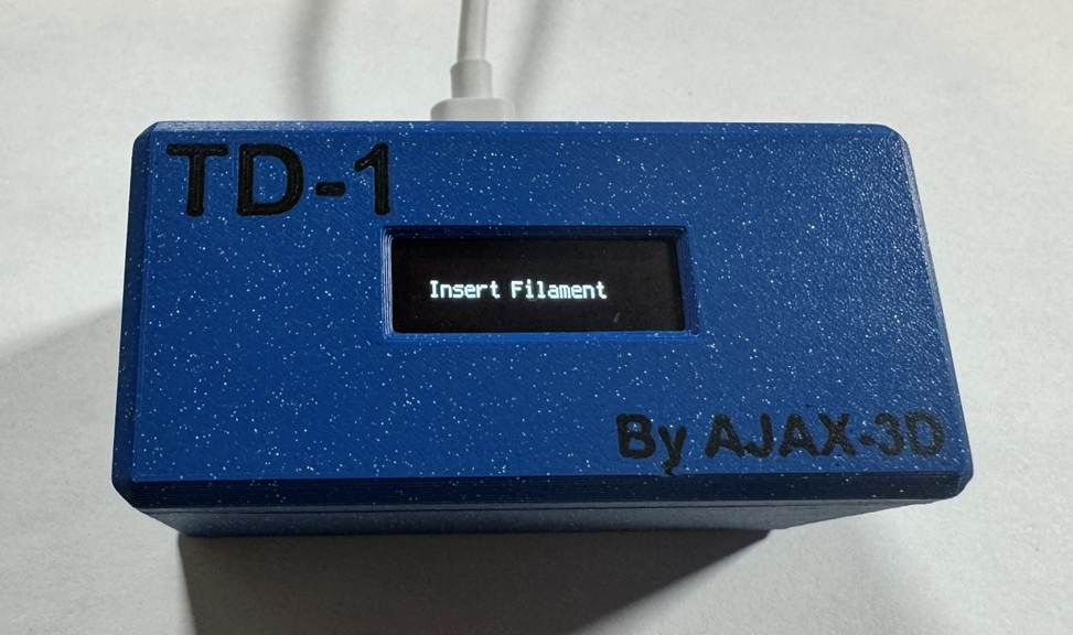
Connect the provided USB-C cable and connect the TD-1 to your PC. Your TD-1 should now show “Insert filament”. Congratulations! Your TD-1 is now complete!